Sunday, 24 January 2016

Heatbed thermistor

I was planning to get a silicone pad heater and machined aluminium plate but I could not find a nice plate with decent price. So I had to go with a traditional PCB with glass plate. I ordered PCB Heatbed MK2B and a bunch of NTC 3950 thermistors. I will use the rest of the thermistors with my environment control unit.

The power wires were easy to solder but I might have bought a bit too heavy wire for it. I use 4 sq mm wire between RAMPS and heatbed. That is pretty much the thickest fitting in the RAMPS screw terminals but it isn't very flexible and might cause me headaches when I try to clean up the wiring mess.

Most of the instructions use Kapton tape to attach thermistor to the heatbed. Unfortunately, I have none here so I had to improvise. I soldered the thermistor to a longer wire with heatshrink and thermal protective sleeve. Then I placed the thermistor in the PCB with some heat resistant grease as I did not have any thermal paste either. I secured the wire in place with some masking tape and then I added good amount of bathroom silicone on the wires. According to the label the silicone is good till +180 C degrees.


Not very pretty but seems to hold pretty well. I hooked up the wires to RAMPS and heated the bed up to 95 C degrees and everything worked ok. In any case this part is hidden so the appearance does not really matter.

Saturday, 23 January 2016

XYZ complete

The second batch of LM8UU bearings arrived and I was finally able to assemble both X and Z axises. Y axis was completed earlier. The second set of 12 LM8UU bearings was not much better but I was able to find enough bearings with suitable tolerances.

X axis ends and carriage were some 3D printed parts I got from a friend. I also had another set but this one seemed to fit better. In any case I am planning to replace those and X belt bearing with better ones as soon I get the printer productive.


Thursday, 31 December 2015

Missing parts

Xmas holiday, family illnesses and some missing bits have kept this project on hold for a moment. I was about to assemble X and Z axises but the horrible quality of LM8UU put me off. I decided to order another batch of bearings from a different seller. Hopefully they will a bit better quality. I have been also waiting quite long some electrical supplies like heat protective sleeving and heat shrinking tube. Finally,  those arrived today and I will be able to solder some of the wires soon.

Friday, 4 December 2015

A4988 drivers and Vref adjustment

After verifying the LCD works I went forward with electronics. I placed the heat sinks on the A4988 drivers and plugged them on the RAMPS board. Based on the instructions and markings I placed them right way and started to think about Vref adjustment. This is for the motor current and I followed the instructions on the RepRapWiki. My drivers have Rs=100 Ohm and I wanted to start safe with 0.7A so I adjusted them to have Vref of 570mV.

A4988 drives with heat sinks

Marlin firmware

In order to get Arduino Mega clone and RAMPS board to function properly I need to install a firmware to Arduino. There are several choices but I decided to start with Marlin. It seems to be actively maintained and has good support.

I downloaded release version 1.0.2 and started to work with the configuration file. I did not modify too many settings at this point. I only selected correct motherboard settings and enabled LCD support. After uploading the firmware I disconnected Arduino and pressed the RAMPS board on it. I also hooked up the LCD screen cables and powered everything up. The LCD lit up and the menu was operational so I guess it works ok.


Thursday, 3 December 2015

Electronics arrived

We had a postal strike here in Finland so not much happened for a while. But today I got some packages! My Arduino Mega clone, RAMPS and bunch of other stuff arrived.


I have an original Arduino UNO so the Arduino IDE was already familiar to me. I'll leave installation of the electronics for the weekend but I wanted to test the Mega board first. But it did not work straight away with OS X 10.9. The simple LED blinking code refused to upload to the board. The error was following:

avrdude: ser_open(): can't open device "COM1": No such file or directory ioctl("TIOCMGET"): Inappropriate ioctl for device

So after a couple searches I learnt I should install a new USB driver. The instructions and driver can be found here: http://kiguino.moos.io/2014/12/31/how-to-use-arduino-nano-mini-pro-with-CH340G-on-mac-osx-yosemite.html

After running the installer and reboot the Arduino IDE was able to upload the code and LED blinker works fine now.

Saturday, 21 November 2015

Lubrication and hammering

Finally I cut most of the 8mm smooth rods. First I tried with hacksaw with bimetal blade but that was just polishing the shaft. So I ended up using Dremel with 0.4mm cutting wheel. Actually several wheels as they were some no-name cheap ones and many of them shattered. A good reason to use safety glasses.

With Y-axis rods done I was able to try out LM8UU the bearings. As mentioned earlier, I bought some very cheap ones and they definitely behaved like that. Replacing them with better ones or with IGUS is on my todo. I cleaned up the linear bearings and lubricated them with lithium based grease. As an afterthought the grease might have been a bit too thick and sticky for such small bearings.

Y-axis rods in place

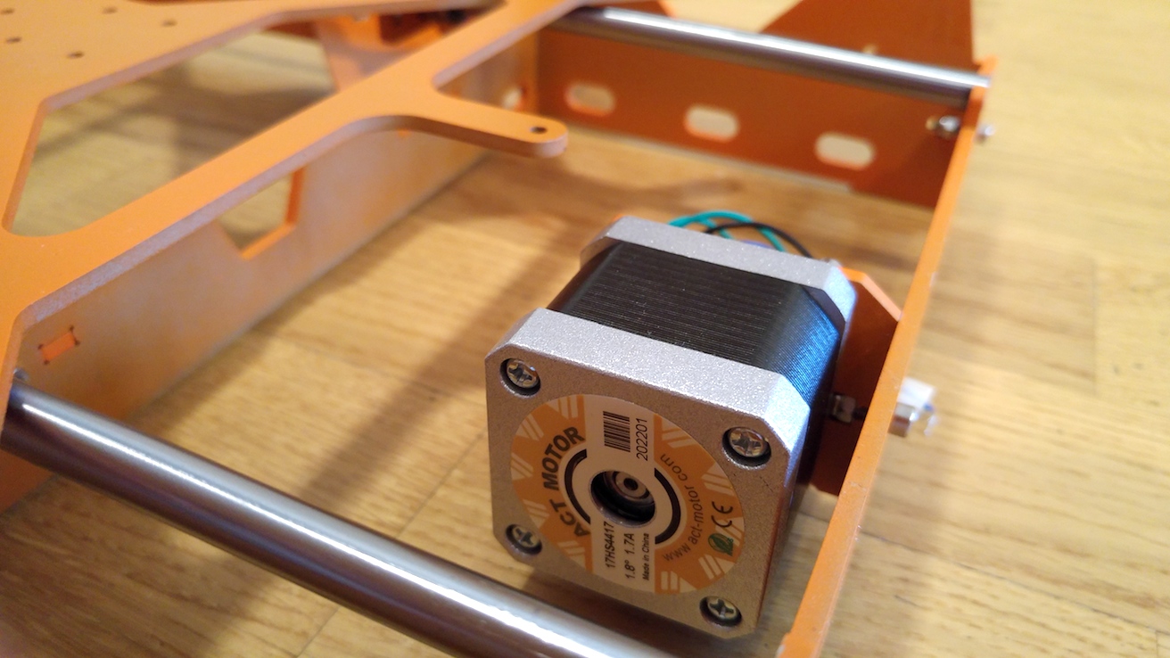
After hammering the rods in place I also installed the first stepper motor. I bought a package of five stepper motors and they are all ACT Motor 17HS4417. They should be ok but I will see later how they perform. I don't expect very high acceleration for Y-axis as the build plate carriage is quite heavy even without any heatbed or glass. I will attach the belt as soon as I get some more printed parts for the carriage.

17HS4417 in place